MBSE Reference
Specification ↔ Design
One solution at two maturities: the solution specified (Specification) facing the solution realized (Design). The digital thread is the set of links that holds the two together.
What must be true, and how we will prove it.
Needs, performance and constraints; textual and parametric. The input problem.
What the system must do and how it decomposes: functions, logical blocks, allocation.
What crosses each boundary: signals, data, power, fluid.
How each requirement is proven: Analysis, Inspection, Demonstration, Test.
How the specification is realized.
New requirements the design generates, which refine the specification for the next level down.
Schematics, pins, wiring, harness, formboard.
PCB layout and digital / FPGA verification.
3D geometry, packaging, structure.
Hydraulic / pneumatic / fuel schematics and routing.
Architecture and implementation.
“Today’s design is tomorrow’s specification.”
Requirements live on both sides: input requirements on the left, derived requirements on the right. Each design refines the specification for the next level down, and Teamcenter Requirements is the record for both.
Governs both sides · owns the links
Teamcenter (PLM)
The digital thread is this web: every specification traced to the design that satisfies it and the evidence that verifies it. Teamcenter holds both sides under one configuration and keeps the links unbroken.
↓Derive
Design generates derived requirements that refine the specification for the next level down. The conversation recurses: today's design becomes tomorrow's spec.
→Satisfy
A design element answers one or more specification items. The solution points back at the specification it satisfies.
←Verify
A specification item is proven against the realized design by Analysis, Inspection, Demonstration or Test. Evidence closes the loop.
The separation is not just good practice. Standards such as DO-331 define a Specification Model and a Design Model as distinct artifacts, and a given model cannot be both. The design must be kept separate from the specification.
The duality above, made concrete: Cameo to Capital
The Specification and Design duality above is abstract by design; it applies whether the design side is electrical, mechanical, or software. On the electrical path specifically, that duality plays out as two detailed, numbered workflows that hand off to each other directly.
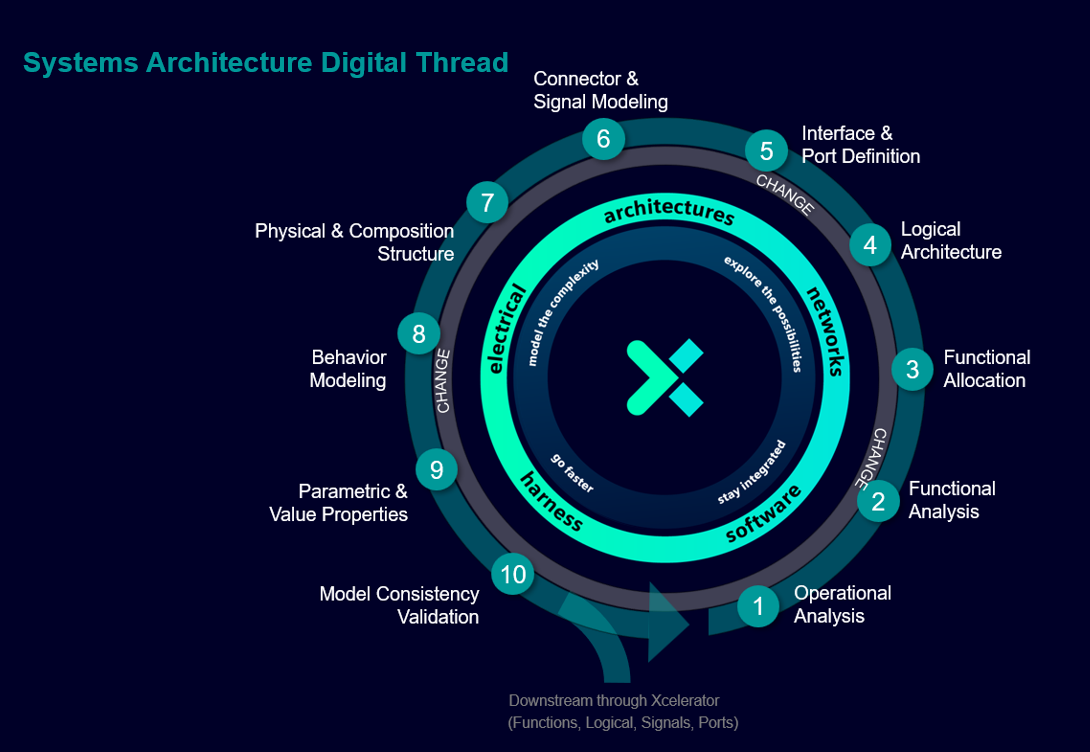
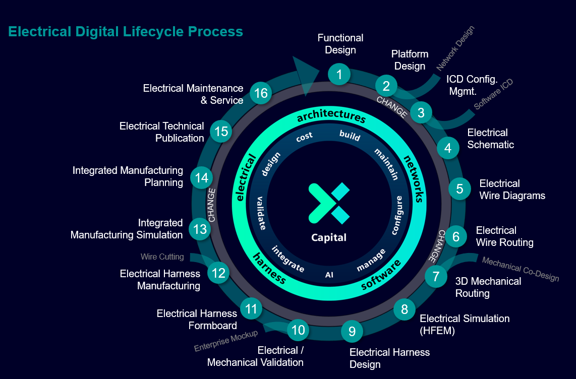
Inside Cameo, the Systems Architecture Digital Thread runs ten steps from Operational Analysis to Model Consistency Validation, the functional and logical specification work in the duality above. Inside Capital, the Electrical Digital Lifecycle Process picks up from there and runs sixteen steps to a manufactured, maintained harness, the design side. The two wheels connect on the same four things that cross every digital thread: Functions, Logical structure, Signals, and Ports.
The Cameo → Teamcenter handoff has been exercised across dozens of real Check-Ins and publishes on a live Teamcenter, every result verified by reading it back from the server, and as of 2026-08-28 every object kind the live connector mapping declares has a graded, evidence-backed verdict: structure, behavior, interfaces, parameters (including definition binding and value write-back on the round trip), diagrams, and Generalization all cross correctly when modeled to spec; the SysML block kinds (System, Subsystem, External, Domain) collapse to one Teamcenter type with the kind preserved in an attribute. What does not cross, with evidence: Refine and Trace (declared, proven dead with controls), UAF IsCapableToPerform (no rule exists), and UAF conformsTo (declared, never observed to cross). A function's full pin/signature still has nowhere to live in Teamcenter. Full detail, including the graded ledger and the SOA reads that prove each entry, in the Modeling in Cameo guide, Section 6.5.
A UAF model built from the real UAF template pushes into Teamcenter cleanly: performers, functions, ports, connectors, services, standards packages, and the Resources domain views all land as their own native Teamcenter types (the Eml0 family), with two caveats worth knowing before relying on it: a Resource Exchange conveys its signal but carries no endpoints (the wiring is recoverable from the connector's ends), and the mapping matches exact stereotype names only, so an element kind without its own mapping row lands as nothing rather than as its parent kind. The Operational domain has no mapping at all.
Whether a Cameo model can later split into shared and used projects, something almost every program eventually needs, is a direct, checkable function of how it's packaged. Package by phase or element type (a "Functional Architecture" tree, a separate "Requirements" tree) and Cameo's own Export Packages wizard reports Error-level violations across four kinds of cross-package coupling, with no in-dialog way to resolve them. Package by function instead and it mostly just works. Full guidance in the Modeling in Cameo guide, Section 3.8.
A flow property (declared on the Interface Block that types a port) is the specification of what a connection is allowed to carry: it has a home on the signal-hub path, and defines the ICD. An item flow (drawn on a specific connector) is the instance-level question of which signal actually rides that specific connection: it's a routing fact, not a definition. A model that collapses the two loses that distinction, which is why they stay separate objects in Teamcenter rather than converging into one. Deciding otherwise was tried and backed out.